
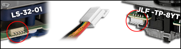
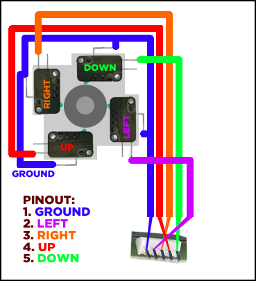
Many Japanese cabinets (or well built console Arcade sticks) use a JST 5-pin connector that will install a SANWA JLF or a Seimitsu LS-32-01 quick and easy (see the picture above) in their control panels.
So? Well, sometimes you want to mix it up, and bring in something without that handy 5-pin JST-H connector available. There are some very nice sticks out there, like the SUZO 500 (it's ugly, but very hard to beat for shooting games) that with a custom shaft can blend in like a good weave in your cabinet. I will use my custom built stick for this guide, but any stick using 4 microswitches can be hooked up this way.
Soldering iron / soldering station
Crimp tool, or a pair of flat pliers
1 x male JST H-connector (if you have a busted JLF or LS-32 it can be soldered off quite easily)*
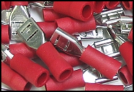
8 x .187" terminal sleeves (1 for each direction and 4 for the grounds, this is the most common size for switches used in sticks)
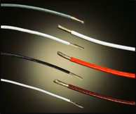
Wire (I recommend you get one colour for the ground and one or more for the directions)
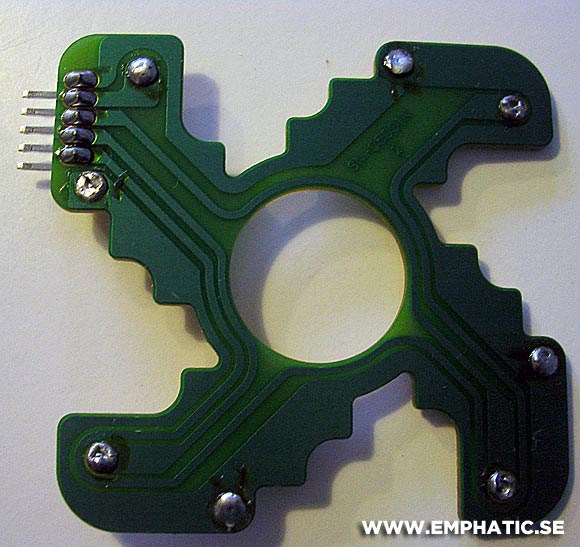
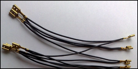
*If you don't have any JST connectors, you can get the kind of PCB connectors pictured below and they will fit as well. I'll try to find some better alternatives and add to this guide. If you try this and find some, please e-mail me as it'll help others. : )

If you can't find a JST connector, I suggest you get hold of a SANWA or Seimitsu PCB and keep reading below.
As you think about the part list above I'd like to show you my new and improved solution using a Japanese SANWA JLF PCB instead.
Soldering iron / soldering station
Parts needed:
1. JLF PCB (Seimitsu LS-32-01 PCB should work, I didn't have any spare ones)
2. 8 short wires with .187" terminals (I had some from a daisy chain harness)
1. De-solder all microswitches from the PCB

2. Have a look if the PCB will fit on the stick you want to use it for (also useful to see how long the wires need to be

3. Get your wires ready
4. Solder these 8 wires to the holes in the PCB where the microswitches were seated before
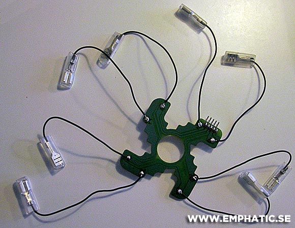
5. Fit it to your joystick and make sure to set the directions on the correct microswitch (below is my beloved hand-made stick).

FINISHED!
Take the wire you want to use for all ground (the COM on the microswitch) and crimp one of your sleeve connectors to the end. If you want to, you can then put this on one of the microswitches on your joystick and measure up the distance to the closest switch on the joystick. Fold the wire and crimp another sleeve connector on it. Continue to the third and forth wire and then pull the wire up to your first one where you will cut it.
Now that all wires are hooked up to the switches, make sure they can be pulled off the switches without the wire length making it impossible, then use electrical tape or tie them together so they are neatly bundled up.
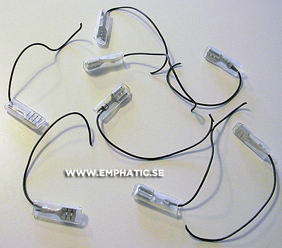
When everything is done, it should look like the picture below (where the SUZO 500 stick is hooked up to the cabinet's connector) only prettier as I did a poor job on that particular harness. :P

It should also work now.